What is UML and Why Use Class Diagrams?
What is UML? Unified Modeling Language, or UML, is a multifunctional developmental modeling language in software engineering. It’s intended to provide a standard way to visualize the design of a system. Developers use UML during the design stage of a software application to clarify requirements, streamline implementation, and prevent bugs. UML contains plenty of diagrams to implement, but Class Diagram is most effective for object-oriented programming languages like C#.
Benefits of Using UML Class Diagrams
There are many benefits to using UML Class Diagrams, and they go beyond just visualizing relationships between classes. Some of the key benefits include:
- Encapsulation: The Class Diagram encourages encapsulation, which means that data and behavior are contained within the same class. This makes it easier to manage complexity and prevents code duplication.
- Reusability: The Class Diagram promotes the reusability of code, which means that you can use the same class in different parts of your program without having to rewrite it. This saves time and reduces errors.
- Abstraction: The Class Diagram allows you to abstract away implementation details and focus on the essential features of the system. This makes it easier to reason about the program and to communicate with others.
- Maintainability: The Class Diagram can help you design software that is easier to maintain over time. By visualizing the relationships between classes, you can identify potential areas of the program that may require changes and plan accordingly.
- Communication: The Class Diagram is a powerful communication tool that allows you to share your design ideas with other developers, stakeholders, and clients. By using a standardized visual language, you can ensure that everyone is on the same page.
Class Boxes
Class Boxes are the main element of a Class Diagram. A class box typically consists of three sections – the class name, the attributes and their types, and the methods and their return types. Access modifiers are expressed using the operators +: public, -: private, #: protected, and ~: packaged. See Figure 1a for the layout of a Class box.
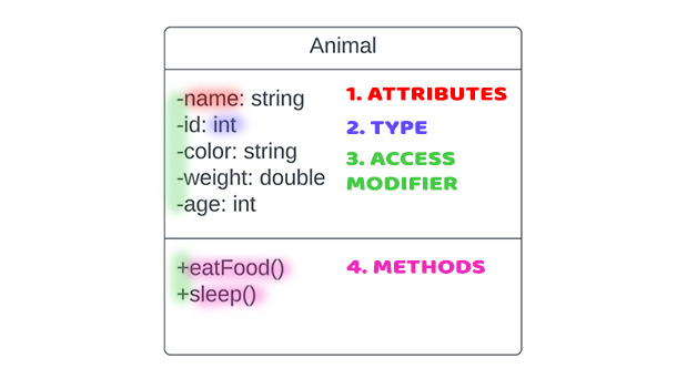
The attributes of a class are the predetermined characteristics that a class has before being run. In the case of our Animal class, we have arbitrarily determined that we want to include the name, ID, color, weight, and age of our animals. The “Type” refers to the data type of the attribute. Some examples of Data Types are integer, string, multiplicity, array, etc. The third box displays the “Method” of the desired class. Methods are what our object does after we click run. It may also contain a return value if desired.

Class Relationships
UML diagrams use arrows to represent types of relationships. Inheritance is the ability of one class (child class) to inherit the identical functionality of another class (parent class) and then add new functionality of its own. In Class Diagrams, a hollow-bodied arrowhead pointing from the child class to the parent class connects them by Inheritance.

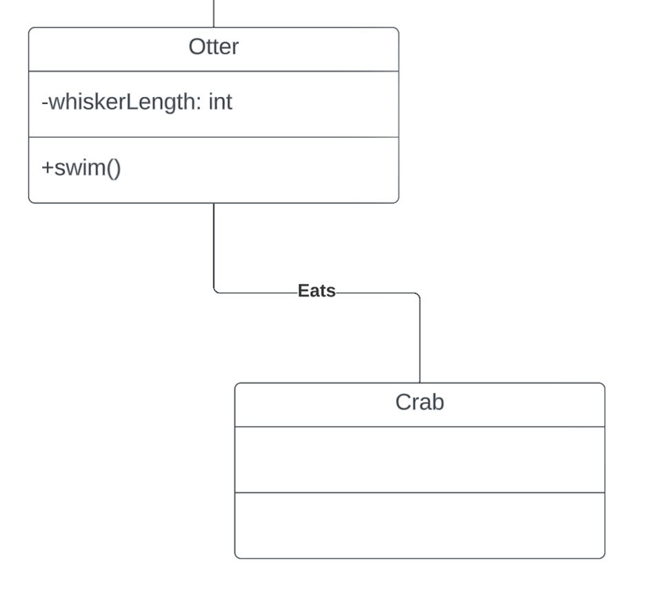
An association relationship between two or more objects denotes a path of communication (also called a link) between them so that one object can send a message to another. Figure 2b demonstrates an association relationship with a standard line. The Otter class interacts with the Crab class, but they exist independently.
Although Aggregation and Compositionhave similar arrows, they have significant differences. Aggregation means one object is the owner of another object, and Composition means one object is contained in another object.

Figure 2c displays a Tortoise class and a Creep (a group of turtles) class having an Aggregation relationship. The aggregation relationship allows the tortoise to be enter the creep, and if the tortoise were to leave the creep, these classes would still exist. The ability of the Tortoise class to join the Creep class as it pleases is impossible during a Composition relationship, demonstrated in Figure 2d.

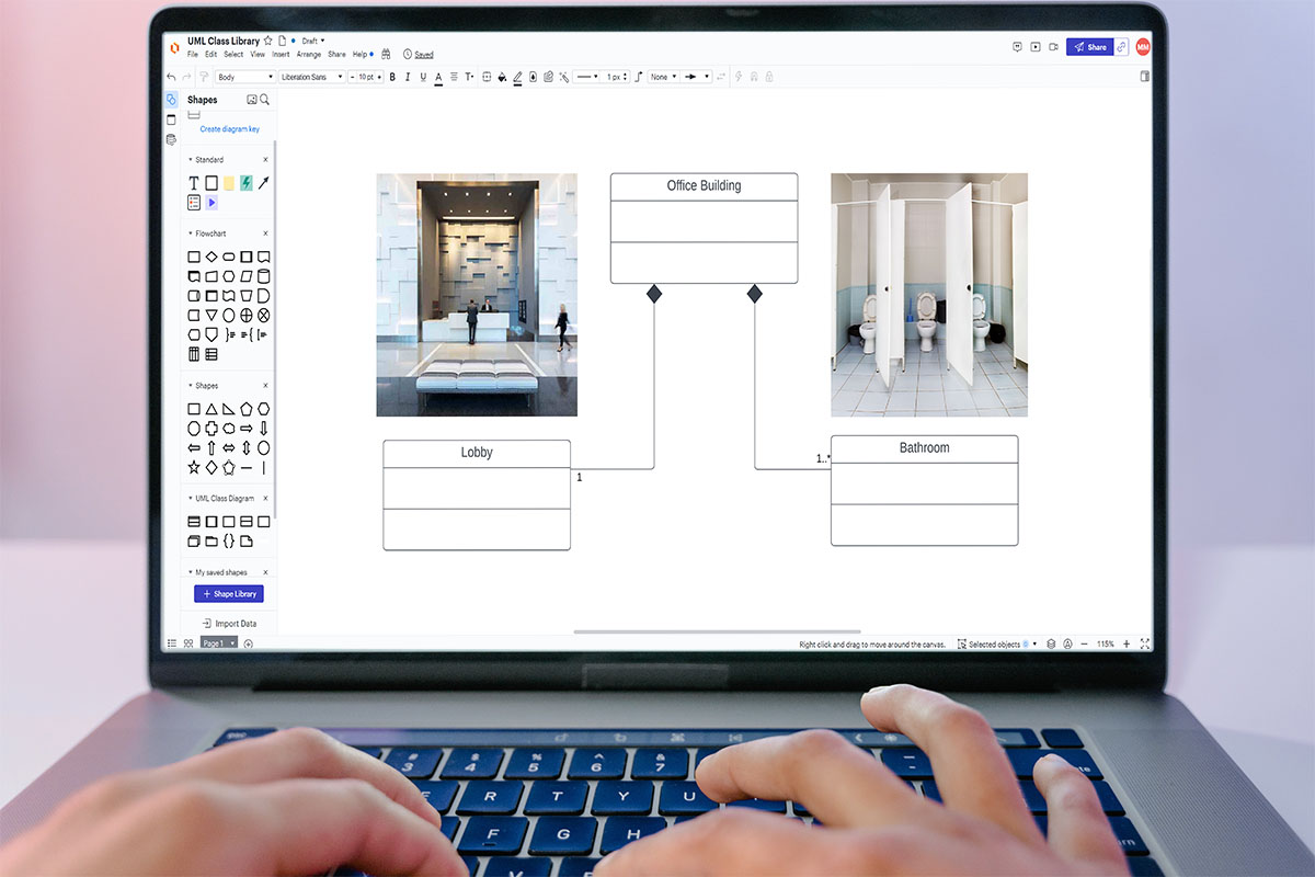
The Office Building class contains the Bathroom and Lobby classes. Because of the Composition relationship, deleting the Office Building would also delete Lobby and Bathroom classes. The Lobby and Bathroom classes are dependent on the Office Building class.
You might be wondering what the “1” or the “0..” means in Figure 2c and Figure 2d. These numbers are multiplicities, and they add an extra element of description within the class diagram.
Multiplicities
Multiplicities help to define the cardinality of relationships between classes and provide a more complete picture of the possible instances of each class. By using multiplicities, designers and developers can ensure that their class diagrams accurately reflect the intended relationships between classes and that their software systems function as expected.
| Possible Values | Meaning |
|---|---|
| 1 | One, no more than one |
| 0..1 | Zero to one |
| * | Many |
| 0..* | Zero to many |
| 1..* | One to many |
Multiplicities add another element of clarity for programmers looking to write code from the Class Diagram. In Figure 3b, multiplicities are the numbers at the start and end of each relationship arrow. For example, in the Composition relationship between the Orders class and the Customer class, there is a “0..*” (zero to many) on the Orders class side and a “1” (one) on the Customer class side. The “1” on the Customer class side represents that there can be only one customer, while the “0..” on the Orders class side indicates that the one customer can have zero orders or any number of orders.
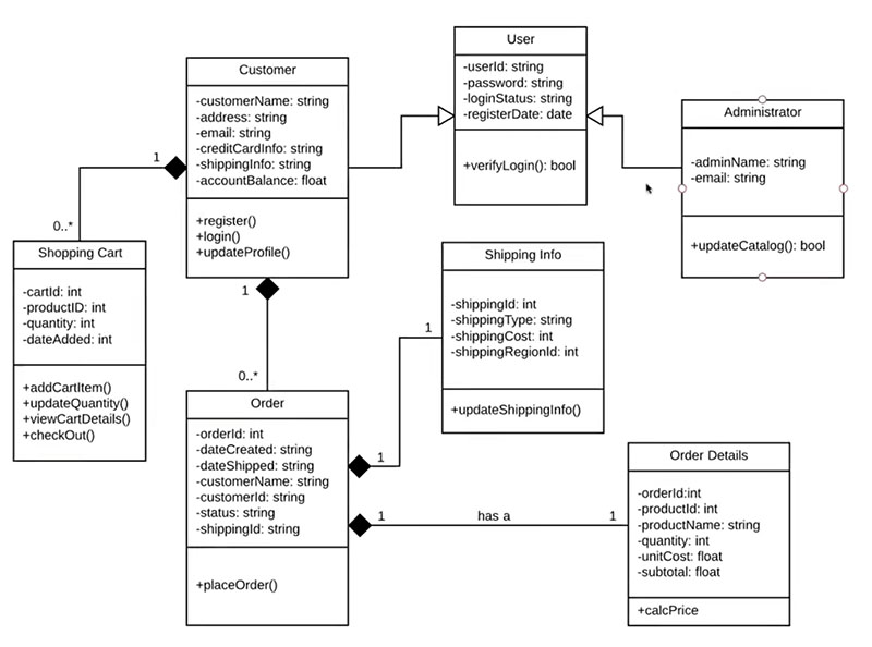
After placing an order, the customer can place an another order, as many as they please. This characteristic also applies to the Shopping Cart class: a user can start with zero shopping carts, place an order, and then create another shopping cart.
Conclusion
In conclusion, UML provides a standard way to visualize the design of a system and the Class Diagram is a great tool for visualizing the relationships between classes in an object-oriented programming system. Lucidchart is a popular tool among developers for creating these diagrams, and it’s important to keep in mind the different sections that can be included in a class box as well as the different types of relationships that can be represented using arrows. If you are a visual learner I suggest following the Lucid Software tutorial, it helped me understand Class Diagrams.
By having a strong understanding of UML Class Diagrams, developers can clarify requirements, streamline implementation, and prevent bugs in their software applications. This means they can more effectively communicate and collaborate with team members and produce higher-quality software products. So, if you’re new to UML Class Diagrams, don’t be intimidated – start by familiarizing yourself with the basics and continue to practice and improve your skills over time.
I hope this beginner’s guide has been helpful and informative. By following the tips and guidelines outlined here, you’ll be well on your way to mastering UML Class Diagrams and improving your software development skills. Happy diagramming!
Helpful Resources!
“UML Class Diagram Tutorial.” YouTube, YouTube, 21 July 2017, https://www.youtube.com/watch?v=UI6lqHOVHic. Accessed 28 Mar. 2023.
“The Best Software Portfolio Idea for a Software Developer Job.” YouTube, YouTube, 28 Mar. 2022, https://www.youtube.com/watch?v=oWp-MeaSSw4. Time 17:52. Accessed 28 Mar. 2023.




[…] more on UML structure here. With no prior knowledge on class diagrams, the Test class will look tricky. However, you will find […]